 | ||||||||||||||||||||||||
| ||||||||||||||||||||||||
| ||||||||||||||||||||||||


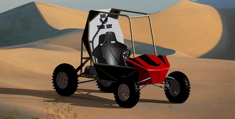
for your eyes only ;) vehicle standing on its shockers ... front GC 17 inches , rear GC 15.5 inches as of now with engine mounted. weight 236kgs , expected weight distribution 45:65 


For those who werent there at virtuals.. our complete vehicle assembly had proved a lot of points to the judges ,, which played a very important part in our teams selection in BAJA 2013. Our vehicle was completely assembled by Subrata Sarkar with little bit help from Narendra Kumar (gearbox) , me (rollcage) and various other inputs from few other team members Sanjay Singh(adams) Asif Khan(CAE) Abhishek Singh(steering) Palash Bolia(steering) Abhishek Upadhyay(rear assembly, powertrain) . our selction had not been possible without this. For juniors. upcoming 4-5 posts like this would help you to understand the strategy we followed during virtuals. this tells the importance to have a complete cad assembly in preliminary round. Special thanx to @subrat for doing the surfacing part (which we will see in FRP)
For those who werent there at virtuals.. our complete vehicle assembly had proved a lot of points to the judges ,, which played a very important part in our teams selection in BAJA 2013. Our vehicle was completely assembled by Subrata Sarkar with little bit help from Narendra Kumar (gearbox) , me (rollcage) and various other inputs from few other team members Sanjay Singh(adams) Asif Khan(CAE) Abhishek Singh(steering) Palash Bolia(steering) Abhishek Upadhyay(rear assembly, powertrain) . our selction had not been possible without this. For juniors. upcoming 4-5 posts like this would help you to understand the strategy we followed during virtuals. this tells the importance to have a complete cad assembly in preliminary round. Special thanx to @subrat for doing the surfacing part (which we will see in FRP)
- Dr. K.C. Vora ;Asst. Director, ARAI
- Dr. Pawan Goenka, President, SAEINDIA and President, Mahindra & Mahindra Ltd
- Mr. Sunil Chaturvedi, CEO & Project Director of National Automotive Testing and R&D Infrastructure
Project (NATRIP)
- Mr. Sunil Patel, M.D. of Lombardini India Pvt. Ltd.
 |
| Mahindra Group Logo (Photo credit: Wikipedia) |


RULE BOOK AT A GLANCE
FRAME
FRAME

Elements of the Roll Cage
- The RRH must be a minimum of 73.6 cm (29 in.) wide at 68.6 cm (27 in.) above the driver’s seat (H-point of driver).
- The roll cage must be a space frame of tubular steel. The required members of the roll cage are:
Primary members : - Rear Roll Hoop (RRH)
- Roll Hoop Overhead Members (RHO)
- Front Bracing Members (FBM)
- Lateral Cross Member (LC)
- Front Lateral Cross Member (FLC)
Secondary members :
must be steel tubes having a minimum wall thickness of 0.89 mm (.035 in) and a minimum outside diameter of 25.4 mm (1.0 in) - Lateral Diagonal Bracing (LBD)
- Lower Frame Side (LFS)
- Side Impact Member (SIM)
- Fore/Aft Bracing (FAB)
- Under Seat Member (USM)
- All Other Required Cross Members
- Any tube that is used to mount the safety belts
- When minimal dimensions are given that is to the centerline of the members, and when a clearance for the driver is given, it is defined by the outside edges of the roll cage members less the padding installed
- Required dimensions between roll cage members are defined by measurements between member centerlines, except where noted.
- As of 2009 the engine has been an unmodified Briggs & Stratton Intek 20 single-cylinder with a displacement of 300cc and power output of approximately 10 bhp (7.5 kW).
- Difference between Pipe and Tube
While it's a cumbersome process to submit your article , and get accepted by wikipedia ( http://en.wikipedia.org/wiki/Baja_SAE )as a highly experienced team of about 10-20 people review it (the thing is, it has only 73 members all over the world :) , and then finally you got an-email that your team Model has been accepted to be featured on wikipedia
Visit the page http://en.wikipedia.org/wiki/Baja_SAE
It's really a proud moment for me as well as my team .
Kudos .
TEAM-KIIT

TO DO LIST-date : 20th jan.
1.Hitch Point (front & rear) - manufacturing & mounting completion Rohit Manglik
2.Chain alignment - Abhishek Upadhyay Mukesh Singh
3.Pedal assembly
4.Throttle stop
5.Head restraint and padding of seat- Narendra Kumar
6.All sharp edges which might endanger the driver, crew, or officials, including "the Wraps", must be eliminated, shielded or radiused. Rohit Rastogi
7.Kill switch mounting
8.brake and reverse light mounting
9.speedometer mounting
10.Fire extinguisher & its mounting Irfan Ahmad
11.Firewall modification as per requirement n discussed - @rohit manglik
12. covering of steering components - Abhishek Singh n rohit manglik
13. side panels
14.engine rpm adjustment n CVT tuning
15.completion of spill prevention
16.Proper routing of brake lining
17.Number paltes (though needed before going to final event , it may be completed as of now)
18. Weld confirmation test (2 samples each) - in our lab . Manish KanwalParakh Kumar Ankit Shaw (complete it by today any how)
19. checking of all fasterners (min 8.8 grade)

1.Hitch Point (front & rear) - manufacturing & mounting completion Rohit Manglik
2.Chain alignment - Abhishek Upadhyay Mukesh Singh
3.Pedal assembly
4.Throttle stop
5.Head restraint and padding of seat- Narendra Kumar
6.All sharp edges which might endanger the driver, crew, or officials, including "the Wraps", must be eliminated, shielded or radiused. Rohit Rastogi
7.Kill switch mounting
8.brake and reverse light mounting
9.speedometer mounting
10.Fire extinguisher & its mounting Irfan Ahmad
11.Firewall modification as per requirement n discussed - @rohit manglik
12. covering of steering components - Abhishek Singh n rohit manglik
13. side panels
14.engine rpm adjustment n CVT tuning
15.completion of spill prevention
16.Proper routing of brake lining
17.Number paltes (though needed before going to final event , it may be completed as of now)
18. Weld confirmation test (2 samples each) - in our lab . Manish KanwalParakh Kumar Ankit Shaw (complete it by today any how)
19. checking of all fasterners (min 8.8 grade)
2.1 Vehicle Configuration:
The vehicle must be capable of carrying one (1) person 190.3 cm (6'3") tall weighing 113.4 kg (250 lb).
2.1.2 Maximum Vehicle Dimensions
Width : 162.56 cm (64 in) at its widest point: Mandatory
Length : 274.32 cm (108 in) end to end: Recommended
2.2 Required Engine
2.2.1 Briggs and Stratton Engine: 10 hp OHV Intake.
2.3 Engine Requirement and Restrictions
A fresh air cleaner element & paper filter are required during On-site Technical Inspection-Engine at BAJA SAEINDIA 2013.
Starter
The Recoil Starter Rope may be extended to accommodate the driver starting the engine while being seated.
Electric start is not acceptable in any case even if it is from B&S standard parts.
2.3.16 Energy Storage Devices Used for Propulsion
Hydraulic accumulators are the only type of stored energy device that may be incorporated into the vehicle for propulsion purposes. If employed, hydraulic accumulators must be at zero energy at the start of each event.
Hydraulic power systems must be properly shielded and documentation of the shielding made available for review.
2.12.2 Transponder Mounting
One transponder will be provided to each team during the endurance event at no cost for the event
purpose. This is essential to use for endurance event for counting the laps during endurance run. The team captain is responsible for returning it, at the end of endurance run. It is the team captain’s responsibility to design a secure and safe mounting for the transponder at given location and acceptable method.
Mounting bracket of sheet metal box of size 55 x 45 x 20mm to be attached/ weld from outside of SIM on Right side of vehicle.

Each transponder as shown (Figure 5) is supplied on the last day of endurance event. However Teams are advised to make a provision of box weld / attached of sheet metal /fiber /plastic of size 55 x 45 x 20 mm on Side Impact Member of frame.
Attaching the bracket with M4/M6 size with Pan / Flat head bolts with lock nuts or fix by strong wire is suggested.The transponder mounting requirements are:
The provision for fitment of transponder is essential to fix it in right position so that it does not come out due to bumps or shaking of vehicle. It’s essential to ensure the signal transmitted by transponder is read by timing
system, so that the purpose of counting laps is not be defeated.
(1) Orientation - The bracket must be mounted vertical to the frame.
The transponder must be mounted on the driver’s right side forward of the seat
(2) Location –no more than 61 cm (24 in.) above the track.
(3) Unobstructed –No obstruction between the antenna on the bottom of the transponder and the ground.
Metal and carbon fiber may interrupt the transponder signal. The signal will normally transmit through
fiberglass and plastic hence it is advice to use it. However if sheet metal box is used it should have cut out
10.2mm (0.4 in.) diameter opening from sensor side.
(4) Protection – Mount the transponder where it will be protected from obstacles.

The vehicle must be capable of carrying one (1) person 190.3 cm (6'3") tall weighing 113.4 kg (250 lb).
2.1.2 Maximum Vehicle Dimensions
Width : 162.56 cm (64 in) at its widest point: Mandatory
Length : 274.32 cm (108 in) end to end: Recommended
2.2 Required Engine
2.2.1 Briggs and Stratton Engine: 10 hp OHV Intake.
2.3 Engine Requirement and Restrictions
A fresh air cleaner element & paper filter are required during On-site Technical Inspection-Engine at BAJA SAEINDIA 2013.
Starter
The Recoil Starter Rope may be extended to accommodate the driver starting the engine while being seated.
Electric start is not acceptable in any case even if it is from B&S standard parts.
2.3.16 Energy Storage Devices Used for Propulsion
Hydraulic accumulators are the only type of stored energy device that may be incorporated into the vehicle for propulsion purposes. If employed, hydraulic accumulators must be at zero energy at the start of each event.
Hydraulic power systems must be properly shielded and documentation of the shielding made available for review.
2.12.2 Transponder Mounting
One transponder will be provided to each team during the endurance event at no cost for the event
purpose. This is essential to use for endurance event for counting the laps during endurance run. The team captain is responsible for returning it, at the end of endurance run. It is the team captain’s responsibility to design a secure and safe mounting for the transponder at given location and acceptable method.
Mounting bracket of sheet metal box of size 55 x 45 x 20mm to be attached/ weld from outside of SIM on Right side of vehicle.

Each transponder as shown (Figure 5) is supplied on the last day of endurance event. However Teams are advised to make a provision of box weld / attached of sheet metal /fiber /plastic of size 55 x 45 x 20 mm on Side Impact Member of frame.
Attaching the bracket with M4/M6 size with Pan / Flat head bolts with lock nuts or fix by strong wire is suggested.The transponder mounting requirements are:
The provision for fitment of transponder is essential to fix it in right position so that it does not come out due to bumps or shaking of vehicle. It’s essential to ensure the signal transmitted by transponder is read by timing
system, so that the purpose of counting laps is not be defeated.
(1) Orientation - The bracket must be mounted vertical to the frame.
The transponder must be mounted on the driver’s right side forward of the seat
(2) Location –no more than 61 cm (24 in.) above the track.
(3) Unobstructed –No obstruction between the antenna on the bottom of the transponder and the ground.
Metal and carbon fiber may interrupt the transponder signal. The signal will normally transmit through
fiberglass and plastic hence it is advice to use it. However if sheet metal box is used it should have cut out
10.2mm (0.4 in.) diameter opening from sensor side.
(4) Protection – Mount the transponder where it will be protected from obstacles.
CONTENTS
Section 1 General Information
Section 2 Vehicle Requirements and Restrictions
Section 3 Roll Cage, Systems and Driver’s Equipment Requirements
Section 4 Competition Procedures and Regulations 26
Section 5 Technical Inspection 28
Section 6 BAJA SAEINDIA Events 31
Section 7 Appendices 37
Appendix 01- Roll Cage Specification Sheet 37
Appendix 02- Local Technical Inspection Rules 38
Appendix 03- Code of Conduct 39
Appendix 04- Virtual BAJA SAEINDIA 40
Appendix 05- Design Report Format 42
Appendix 06- Cost Report Format 43
Appendix 07- Index Sheet for Process Cost Reference 45
Appendix 08- Static Event Participation Sheet 46
Appendix 09- BAJA SAEINDIA 2013 Scoring 47
Appendix 10- BAJA SAEINDIA 2013 Awards 48
Appendix 11- BAJA SAEINDIA 2013 Penalty Structure 49
Appendix 12- BAJA SAEINDIA 2013 Contacts 50
- Proof of manufacturing location will be essentially required to be furnished by the teams on-site upon being so asked for by the officials.

Automobile Workshop
Department of Mechanical Engineering
2. Only those teams, whose management gives an undertaking to allow them to use the workshop facilities, would be allowed to participate without exception.

3. Teams need to submit a list of facilities / equipments in operating condition with the college facilities which will be used to fabricate & assemble the vehicle as per design presented in virtual BAJA event.
Get the doc here
4.During the actual manufacturing and fabrication process, the video clips that covers students working in
college facility need to be furnished in CD-Format during the College Level Technical Inspection.
Wiil be uploaded soon
5.
4.During the actual manufacturing and fabrication process, the video clips that covers students working in
college facility need to be furnished in CD-Format during the College Level Technical Inspection.
Wiil be uploaded soon
5.


PIPE:
Pipe is designated by ID (Inside Diameter) and Thickness . It is used where Heat Transfer needs to be stopped that is why in case where we want to transfer steam from boiler, we use pipes
TUBE:
Tubes are designated by OD (Outside Diameter) and thickness. These are used where we want heat transfer to happen.
Pipe is designated by ID (Inside Diameter) and Thickness . It is used where Heat Transfer needs to be stopped that is why in case where we want to transfer steam from boiler, we use pipes
TUBE:
Tubes are designated by OD (Outside Diameter) and thickness. These are used where we want heat transfer to happen.
Sculpting the die
making a fibre glass mold
Producing the final product in carbon fibre
Material Required :
1).Epoxy resin
2). Plain weave Carbon Fibre Cloth
3). Biaxial weave Carbon fibre
3). Kevlar
4). Sheet Metal
5).Resin Proof Gloss Sealer
6). Die
7). Blue Semi Crystals used in Swimming Pools
8). Angle Grinder
9). A light Sand Paper


It's all about Grinding , Cutting and Welding.....
Team Work :
Manufacturing of Roll cage : Subrat Sarkar, jayantraj
Welding : Parakh Kumar, manish kanwal
Grinding : All Team Members
Chop Saw
The day work started at 9:00am with cleaning the workshop, making proper alignment of roll-cage members, dimensioning using Solid Works ...
All about Grinding :
First of all Grinding machines is a machine tool use for making the surface of workpiece surface even and of high quality. However, there are some roughing applications in which grinding removals high volumes of metal quite rapidly. Thus grinding is a diverse field.
Types:The most commonly used are
1). Disc Grinder/ Angle Grinder / Side Grinder
Angle grinders can be powered by an electric motor, petrol engine or compressed air. The motor drives a geared head at a right-angle on which is mounted an abrasive disc or a thinner cut-off disc, either of which can be replaced when worn. Angle grinders typically have an adjustable guard and a side-handle for two-handed operation. Certain angle grinders, depending on their speed range, can be used as sanders, employing a sanding disc with a backing pad or disc. The backing system is typically made of hard plastic, phenolic resin, or medium-hard rubber depending on the amount of flexibility desired.

Angle Grinders give off a lot of sparks. This is a great hazard to the eyes

Safety goggles must be worn. Angle Grinders should never be used without their guard or handle attached, they are there as a necessary precaution for safety.

A typical Disc Grinder ( 1yr. old)

While grinding, if the soft metals get embedded in the inter-abrasive voids, it can be easily removed with the help of Dressing, i.e. the use of metal brush ..

Bench Grinder


The back side of Disc Grinder is provided with locking knob to help changing the discs ( Flap disc, Grinder Disc , Cutter Disc)
ALL ABOUT WELDING :For manufacturing of BAJA Vehicle this year , we are using Metal Inert Gas ( MIG) Welding also called as Gas Metal Arc Welding (GMAW) or Metal Active Gas Welding (MAG) . This is welding process in which an electric arc forms between a consumable wire electrode and the workpiece metal(s), which heats the workpiece metal(s), causing them to melt, and join. Along with the wire electrode, a shielding gas feeds through the welding gun, which shields the process from contaminants in the air. The process can be semi-automatic or automatic. A constant voltage, direct current power source is most commonly used with GMAW, but constant current systems, as well as alternating current, can be used. There are four primary methods of metal transfer in GMAW, called globular, short-circuiting, spray, and pulsed-spray, each of which has distinct properties and corresponding advantages and limitations.
Equipments :To perform gas metal arc welding, the basic necessary equipment is a welding gun, a wire feed unit, a welding power supply, an electrode wire, and a shielding gas supply.


Team Work :
Manufacturing of Roll cage : Subrat Sarkar, jayantraj
Welding : Parakh Kumar, manish kanwal
Grinding : All Team Members
Chop Saw
The day work started at 9:00am with cleaning the workshop, making proper alignment of roll-cage members, dimensioning using Solid Works ...
All about Grinding :
First of all Grinding machines is a machine tool use for making the surface of workpiece surface even and of high quality. However, there are some roughing applications in which grinding removals high volumes of metal quite rapidly. Thus grinding is a diverse field.
Types:The most commonly used are
1). Disc Grinder/ Angle Grinder / Side Grinder
Angle grinders can be powered by an electric motor, petrol engine or compressed air. The motor drives a geared head at a right-angle on which is mounted an abrasive disc or a thinner cut-off disc, either of which can be replaced when worn. Angle grinders typically have an adjustable guard and a side-handle for two-handed operation. Certain angle grinders, depending on their speed range, can be used as sanders, employing a sanding disc with a backing pad or disc. The backing system is typically made of hard plastic, phenolic resin, or medium-hard rubber depending on the amount of flexibility desired.


Angle Grinders give off a lot of sparks. This is a great hazard to the eyes

Safety goggles must be worn. Angle Grinders should never be used without their guard or handle attached, they are there as a necessary precaution for safety.

A typical Disc Grinder ( 1yr. old)

While grinding, if the soft metals get embedded in the inter-abrasive voids, it can be easily removed with the help of Dressing, i.e. the use of metal brush ..

Bench Grinder


The back side of Disc Grinder is provided with locking knob to help changing the discs ( Flap disc, Grinder Disc , Cutter Disc)
ALL ABOUT WELDING :For manufacturing of BAJA Vehicle this year , we are using Metal Inert Gas ( MIG) Welding also called as Gas Metal Arc Welding (GMAW) or Metal Active Gas Welding (MAG) . This is welding process in which an electric arc forms between a consumable wire electrode and the workpiece metal(s), which heats the workpiece metal(s), causing them to melt, and join. Along with the wire electrode, a shielding gas feeds through the welding gun, which shields the process from contaminants in the air. The process can be semi-automatic or automatic. A constant voltage, direct current power source is most commonly used with GMAW, but constant current systems, as well as alternating current, can be used. There are four primary methods of metal transfer in GMAW, called globular, short-circuiting, spray, and pulsed-spray, each of which has distinct properties and corresponding advantages and limitations.
Equipments :To perform gas metal arc welding, the basic necessary equipment is a welding gun, a wire feed unit, a welding power supply, an electrode wire, and a shielding gas supply.
MAW torch nozzle cutaway image. (1) Torch handle, (2)Molded phenolic dielectric (shown in white) and threaded metal nut insert (yellow), (3) Shielding gas diffuser, (4)Contact tip, (5) Nozzle output face


Subscribe to:
Posts (Atom)


- Follow Us on Twitter!
- "Join Us on Facebook!
- RSS
Contact